L チカさせる LED をどんどん増やして (^_^;) 、ついに 64 個になりました。Arduino スケッチ例「Row-columm Scanning to control an 8×8 LED Matrix」を実験してみましょう。
が、この解説通りに製作してもいまいちうまくいきませんでした。うまくいかない点を改善しながら、実験していきましょう。
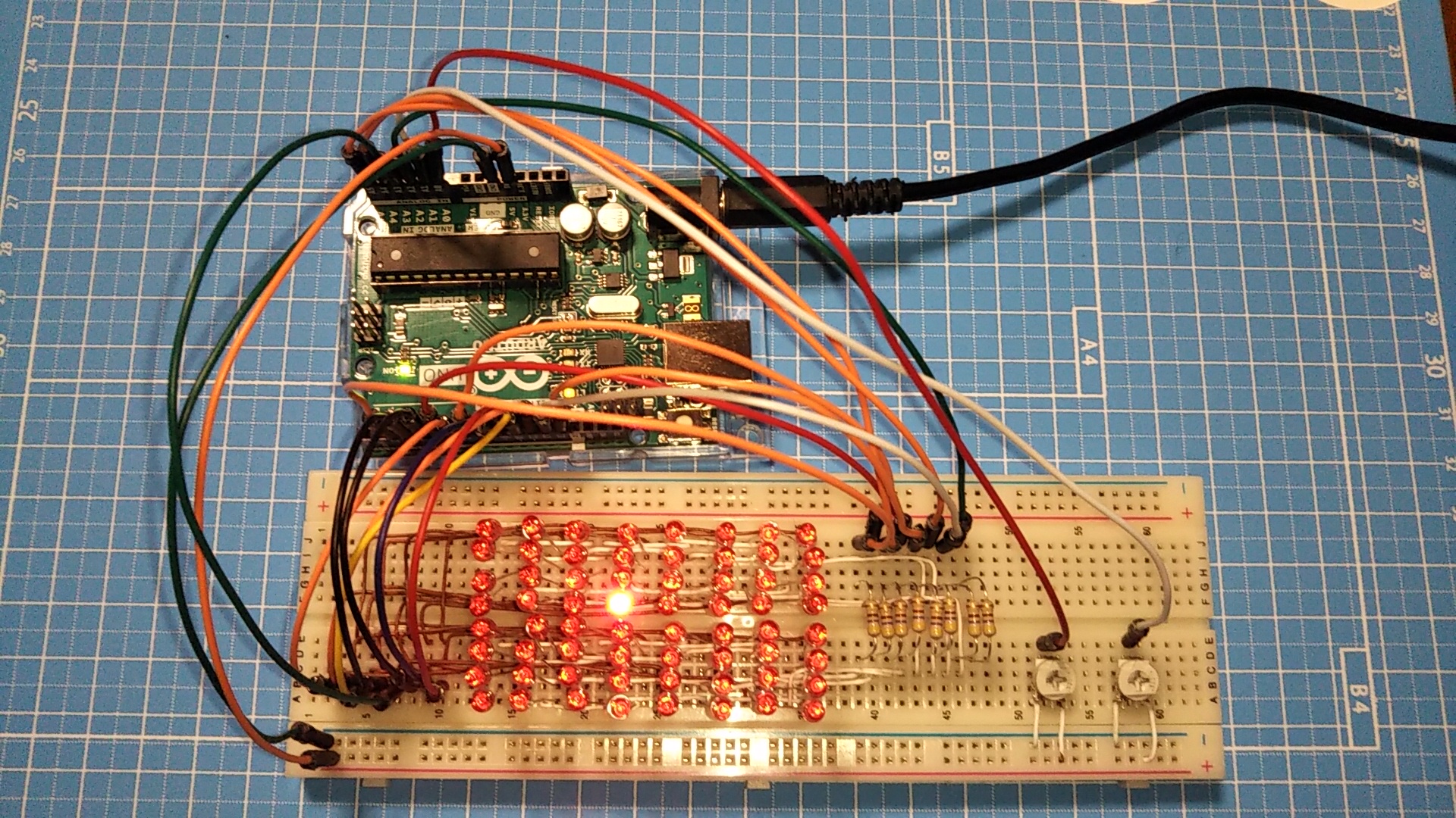
まず完成したブレッドボードです
写真は完成したブレッドボードです。
右にある 2つのボリュームを回すと、その値に応じた位置の LED が点灯します。
スケッチ例では LDM-24488NI (データシート)というマトリクスパネルを使用していますが、俺は持っていません。
でも LED が手元にたくさんありましたので、自分でマトリクス回路を作ってしまいました。ブレッドボード上でこんなマトリクスを組むのはけっこうトリッキーで、あまりきれいになってませんけど (^_^;)
回路の改善点
この回路は、ひとつの Row (行) を HIGH に、ひとつの Column (列) を LOW にすることで、その Row と Column の交差する点にある LED が点灯するというものです。これは「ソース回路」と「シンク回路」の組み合わせですね。ソース側を HIGH 、シンク側を LOW にすることで、ソースから電流が流れ出て LED を通り、シンクへ流れ込みます。
ひとつの LED に着目したとき、アノード側を HIGH (5V) 、カソード側を LOW (0V) にするわけですから、とうぜん電流を制限するための抵抗器が必要です。解説の回路図にはその「とうぜん必要となる抵抗器」がありません。下手をすればマイコンを壊してしまいます。必ず抵抗器を挿入しましょう。
図は、抵抗器を追加して作った回路図です。
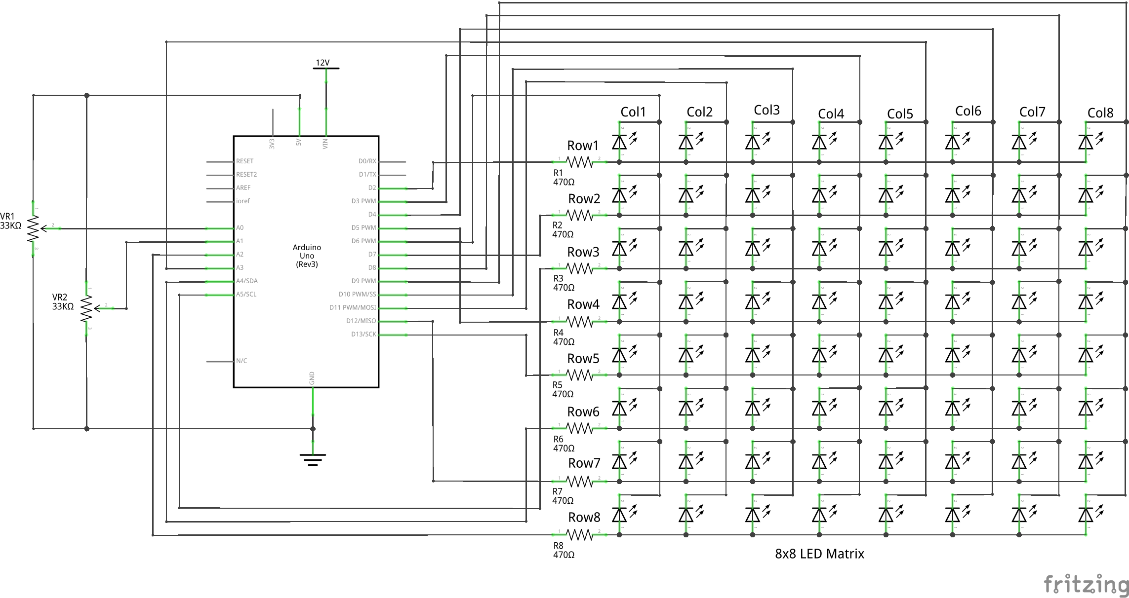
点灯する LED は 1 個だけですので、いつものように電流値を計算すれば OK です。抵抗器は、Column 側でも Row 側でもかまいません。この回路では 470Ω として、6mA 程度の電流を流しています。
なお、IO ポートから取り出せる、あるいは流し込める電流の合計を 100mA とすると、同時に点灯できるのは 16 個までです。実験中に間違ってたくさんの LED を点灯させないように注意しましょう。
スケッチの改善点
スケッチ例を Arduino に書き込んで起動すると、とりあえず動きます。ボリュームを回すと、それに応じて点灯する位置も変化していきます。でも、LED はなぜか薄暗く点灯しているだけです。6mA の電流を流したときの明るさではありません。
スケッチをみてみましょう。
まず、setup() ですべての Column を HIGH にして LED を消灯し、位置変数 Pixels[x][y] をすべて HIGH にします。
loop() では、まず関数 readSensors() で ボリュームの位置を検出し、その位置の変数 Pixels を LOW にしています。そして、関数 refreshScreen() では、ひとつの Row を HIGH にしてから Column を順にチェックしていきます。もしその位置の Pixels が LOW であれば、その Column を LOW にすることで交点の LED を点灯させます。
そしてすぐに Column を HIGH に戻し、Row を LOW にすることですべて消灯して、loop() の最初に戻ります。
点灯時間を長くする
なぜ LED が暗くしか点灯しないのか。それは、LED が点灯してもすぐに消灯されてしまい、一回りチェックし終わるまで消灯のまま待たされるからですね。であれば、もう少し点灯している時間を長くすれば良さそうです。
そこで、下のスケッチのように 105 行目に delay(10); を挿入しました。点灯したときのみ時間待ちさせますので、チェックする時間には影響しません。時間は長いほどデューティ比が大きくなるのでしっかり点灯しますが、ボリュームの変化に対するレスポンスが悪くなってしまいます。
レンジの変更
スケッチを変更したついでに、83 、84 行目の map() のパラメータも変更しました。
スケッチ例の map(analogRead(A0), 0, 1023, 0, 7) では、入力値の 0~5V の範囲を 7 等分することになります。これでは電源電圧が下がったときなど入力値が 5V に届かなかった場合に 8 番目の LED が点灯しません。そこでここは 8 等分することで 8 番目の LED の点灯レンジを下げてやることにします。
変更したスケッチ
ということで、以下のようなスケッチになりました。上記の変更点以外はまったく変えていません。クレジットも変更していませんので、再利用にはご留意下さい。
なお、こうしたマトリクスを制御するライブラリもあるようです。ライブラリを利用することで、もっと簡単でエクセレントなスケッチにできるかもしれませんね (^_^;)
- /*
- Row-Column Scanning an 8x8 LED matrix with X-Y input
- This example controls an 8x8 LED matrix using two analog inputs.
- This example works for the Lumex LDM-24488NI Matrix. See
- http://sigma.octopart.com/140413/datasheet/Lumex-LDM-24488NI.pdf
- for the pin connections.
- For other LED cathode column matrixes, you should only need to change the pin
- numbers in the row[] and column[] arrays.
- rows are the anodes
- cols are the cathodes
- ---------
- Pin numbers:
- Matrix:
- - digital pins 2 through 13,
- - analog pins 2 through 5 used as digital 16 through 19
- Potentiometers:
- - center pins are attached to analog pins 0 and 1, respectively
- - side pins attached to +5V and ground, respectively
- created 27 May 2009
- modified 30 Aug 2011
- by Tom Igoe
- This example code is in the public domain.
- http://www.arduino.cc/en/Tutorial/RowColumnScanning
- see also http://www.tigoe.net/pcomp/code/category/arduinowiring for more
- */
- // 2-dimensional array of row pin numbers:
- const int row[8] = {
- 2, 7, 19, 5, 13, 18, 12, 16
- };
- // 2-dimensional array of column pin numbers:
- const int col[8] = {
- 6, 11, 10, 3, 17, 4, 8, 9
- };
- // 2-dimensional array of pixels:
- int pixels[8][8];
- // cursor position:
- int x = 5;
- int y = 5;
- void setup() {
- // initialize the I/O pins as outputs iterate over the pins:
- for (int thisPin = 0; thisPin < 8; thisPin++) {
- // initialize the output pins:
- pinMode(col[thisPin], OUTPUT);
- pinMode(row[thisPin], OUTPUT);
- // take the col pins (i.e. the cathodes) high to ensure that the LEDS are off:
- digitalWrite(col[thisPin], HIGH);
- }
- // initialize the pixel matrix:
- for (int x = 0; x < 8; x++) {
- for (int y = 0; y < 8; y++) {
- pixels[x][y] = HIGH;
- }
- }
- }
- void loop() {
- // read input:
- readSensors();
- // draw the screen:
- refreshScreen();
- }
- void readSensors() {
- // turn off the last position:
- pixels[x][y] = HIGH;
- // read the sensors for X and Y values:
- x = 7 - map(analogRead(A0), 0, 896, 0, 7);
- y = map(analogRead(A1), 0, 896, 0, 7);
- // set the new pixel position low so that the LED will turn on in the next
- // screen refresh:
- pixels[x][y] = LOW;
- }
- void refreshScreen() {
- // iterate over the rows (anodes):
- for (int thisRow = 0; thisRow < 8; thisRow++) {
- // take the row pin (anode) high:
- digitalWrite(row[thisRow], HIGH);
- // iterate over the cols (cathodes):
- for (int thisCol = 0; thisCol < 8; thisCol++) {
- // get the state of the current pixel;
- int thisPixel = pixels[thisRow][thisCol];
- // when the row is HIGH and the col is LOW,
- // the LED where they meet turns on:
- digitalWrite(col[thisCol], thisPixel);
- // turn the pixel off:
- if (thisPixel == LOW) {
- delay(10);
- digitalWrite(col[thisCol], HIGH);
- }
- }
- // take the row pin low to turn off the whole row:
- digitalWrite(row[thisRow], LOW);
- }
- }